Making a Weather Station – Telesto Project Part 1
Ever since I moved into my current apartment, I've been wanting to make a simple weather station to put on my balcony. My building is next to a nature reserve and there are no other tall neighbors nearby. There are days when the wind is so strong that it's impractical to stay on the balcony, especially in winter time.
I want to be able to analyze wind speed and direction data, see if I can find patterns, just for fun, without any major purpose behind it. Once I have a weather station, why not add other sensors? Maybe measure the amount of rain, light, atmospheric pressure, etc. Since I currently live in London, a city famous for its rain and gray skies, I might find interesting data here. Going further, who knows, maybe I can create a replica of the station and put it in Recife, my hometown, to see the drastic differences (and similarities) between the two climates.
The first step in my creation process was to define the data I wanted my station to collect, in order of priority: wind speed, wind direction, amount of rain, and light. Then, I did a quick search on the internet to see what has already been done in this area, to learn a little from those who have already explored a similar project.
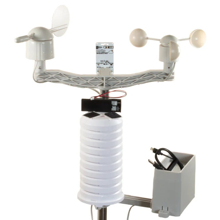
One of the first results I found was this weather station kit for sale at Pimoroni. They basically use a "tower" for each type of sensor, one for the anemometer, a sensor that measures wind speed, one for the anemoscope, a sensor that measures wind direction, one for the rain gauge, a sensor that measures the amount of rain and, finally, a tower for a special board called "enviro weather", which measures temperature, pressure and humidity (with a BME280), and luminosity (with an LTR-559). All of this connects to a Raspberry Pi Pico W, which processes the information and sends it to a specific application or something similar.
This station seems very complete for what I want, but I can see a few things that I would change, since I want to make my own. The first point is that this will be on my balcony, in the field of vision of anyone inside the apartment at all times, so I don't want a visual cacophony that makes my balcony look like one of those rooftops full of antennas that no one knows what they're for anymore. Not that I'm naive enough to think that I'll be able to think of something better than the Pimoroni station or that, even if I do think of something better, I'll be able to execute my ideas with excellent fidelity, but at least I'll be able to say at the end of everything that I tried.
I made some conceptual drawings of the direction that I think could be interesting to follow, but keep in mind that they're just concepts.
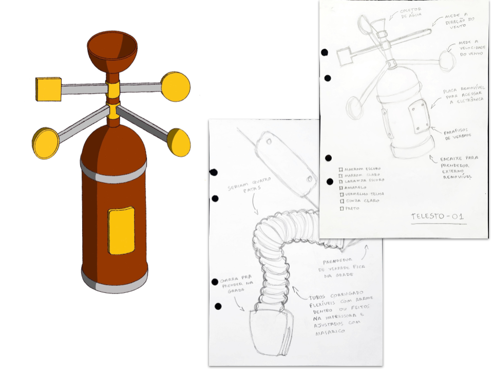
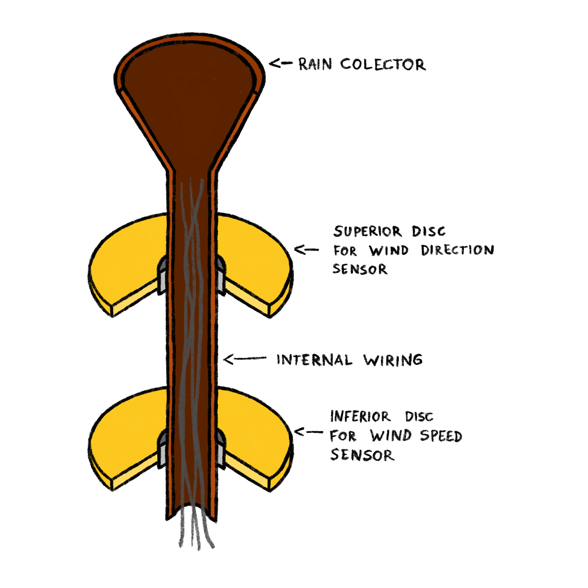
The most important direction I see in this concept is to reduce as much as possible the number of towers that the station will have. If possible, I'd like to have just one, which requires that this tower be hollow so that the sensor wires and tubes can pass through it.
However, this design will depend on how I will develop the sensors. They will define the limitations that I will have to accommodate in the final design, so let's start this project by exploring ideas for each of the sensors.
Anemometer
An anemometer is basically a wind vane connected to a speed sensor. As the wind vane rotates more, we can say that we are detecting a faster wind. This measurement can then be compared with a stable source of wind, whose speed is already known, so that we can calibrate our speed sensor and report the data collected in already established units, such as Km/h, knots, etc.
The fundamental point of the anemometer is, then, to measure speed. But how can we do this? One option is to buy a ready-made speed sensor, another is to explore some ideas that go deeper into the most fundamental concept of speed: variation of position in time, or, as we learned in school, "delta S over delta T". This means that if we can measure the (angular) position of the pinwheel over time and send it to a microcontroller or microprocessor, such as an Arduino or Raspberry Pi, it should be able to calculate the speed from these positions and the time the change lasted.
A very common way to measure the position of a rotating element, such as a motor, is through an encoder. Encoders can be made in many ways, but the most common ones use potentiometers, which are basically a device that changes its electrical resistance as its shaft rotates, so it is possible to associate each resistance value with a position.
The problem with potentiometer encoders is that they tend to have a very high resistance to movement, you need to apply a bit of force to turn them. This makes it difficult to use in our application because we need to be able to make a pinwheel that rotates even in weak winds, in order to be able to detect these winds.
Another type of encoder that may be more suitable for our application are magnetic encoders, which, as the name suggests, calculate the direction and magnitude of the magnetic field around them. In practical terms, you place a magnet on the shaft of the part whose rotation you want to measure and leave the encoder close to the magnet, but outside the shaft, in a place where it will not rotate. As the magnet rotates with the shaft, the magnetic field it produces will rotate in relation to the encoder, changing its direction and magnitude. Then you can associate each of these values with a specific position. Viewing the application of this encoder can help a lot in understanding.
For applications like ours, where we do not want to add resistance to the rotation of the wind vane, the magnetic encoder seems like a great idea. But, if we look at it in a practical way, it can cause us problems when assembling the climate station following the direction presented in the concept at the beginning of this post, which suggests only a tower, with the sensor wires and tubes passing through it. The magnetic encoder commonly sold uses several wires to communicate with the board that will serve as the brain of the station (the microcontroller), which can be a high number depending on the thickness of the tower. For now, this is not a problem in itself, but a risk.
Still on the idea of exploring our options, we can think of another way to use magnets to measure speed, but without using the magnetic field magnitude and direction sensor. There is a type of switch called Reed switch that "turns on" a circuit when a sufficiently strong magnet passes close to it. If we use some Reed switches associated with resistors with unique values, we can generate a unique electrical voltage value for each position of the magnet. We can visualize this better in the circuit below:
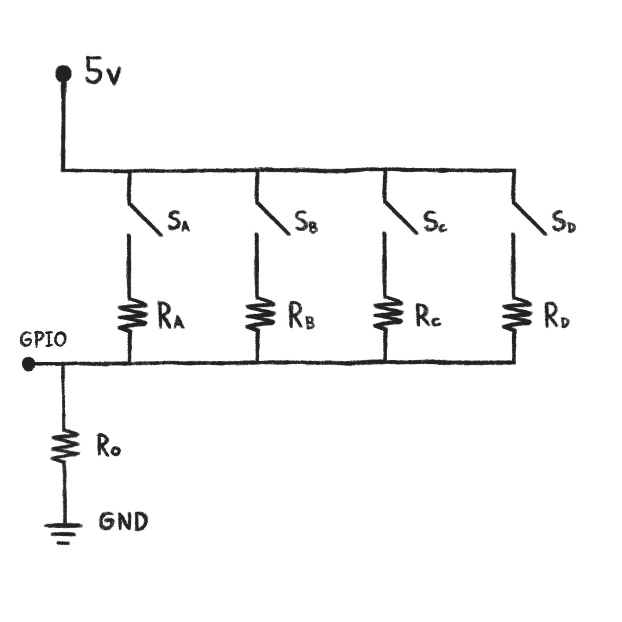
In this circuit, if the magnet is on top of Reed switch A (Sa), then only this path will flow with electric current. Since we have resistor A (Ra = 440 Ω) and zero resistor (R0 = 220 Ω), the voltage measured by the microcontroller (GPIO) will be 1.667 v.
When the magnet leaves Reed switch A (Sa) and goes to Reed switch B (Sb), the electric current starts to flow through path B, which has resistor B (Rb = 110 Ω) and zero resistor (R0 = 220 Ω), hence, the voltage measured by the microcontroller changes to 3.333 v.
If each Reed switch has a single-value resistor associated with it, the voltage value measured on the microcontroller will also be unique. So we can map this single voltage value to find the position of the magnet.
If you want to learn more about this simple circuit that uses two resistors in each path to generate electrical voltage of specific values, it is worth searching for voltage divider circuit. Something similar happens in the so-called simple digital-to-analog converters.
The interesting thing about this approach is that it only needs three wires: a Vcc (5V), a GND (ground) and one that carries the signal (GPIO), the voltage value between the resistors. This requires the microcontroller to have an analog port to receive this signal, but this is quite common on today's boards. The disadvantage, of course, is that it is much more complex to assemble than using a simple magnetic encoder that is ready to go.
Anemoscope
The anemoscope is the instrument that will measure the direction of the wind. This can be done using the same approach as the Anemometer. In this case, it is even easier: while with the Anemometer we need to measure the position over time to calculate the speed, with the Anemoscope we only need the current position, without needing to take the time interval into consideration.
Rain Gauge
The rain gauge is the instrument responsible for measuring the amount of rain that falls in a given region. This amount is usually given in millimeters of water, that is, to measure the amount of rain, simply leave an open container in the middle of the rain and, using a ruler, measure the depth of the accumulated water. This is the value of the amount of rain.
But how can we do this automatically, so that our weather station doesn't need to have arms and legs to go and get a ruler and measure the water column? Although, now that I write this, I think a weather station with arms and legs is an excellent idea, it would take me much longer than I expected to finish a project like this. So let's follow a simpler approach, which is commonly used in weather stations out there, including Pimoroni and the old Brazilian project PluviOn.
The idea is to collect water in a mobile container that sits on an axis. The combination of the axis with the shape of the container makes it a bistable system, like a seesaw, capable of finding stability on both sides. We can visualize this better in the animation below, as the water falls and one side of the container fills, the weight of the water changes the center of gravity of the system, to the point where it rotates on the axis, dumping the accumulated water on that side. The cycle then starts again, but this time on the opposite side of the container.
Once we build a system like this, we can count how many times the container changes sides, knowing that each change represents the accumulation of a specific amount of water. This means that our measurement will be made in intervals, if the container rotates with 20 mL of water, we will only be able to measure the amount of rain every 20 mL.
The counting can be done in several ways, one of them is using approaches similar to the one we explored in the Anemometer and Anemoscope position sensor: a magnet is glued in the middle of the collecting container and a reed switch is attached outside the container, in the fixed part. Every time the container changes sides, the magnet will pass through the switch and generate an electrical signal that we can send to the microcontroller. Approaches with encoders also work, since we can use them to observe the rotation of the container.
Luminosity
This is perhaps the simplest to explore. A simple light-dependent resistor (LDR) can vary its electrical resistance depending on the light it receives. A more interesting option might be to use the LTR-559 together with the BME280, to be able to measure temperature, pressure, humidity and light.
Next Steps
In the next post we will prototype some of these ideas we had about measuring the position/rotation of an axis. The goal is to explore the approaches in more detail, understand how to calculate the value of resistors and voltages in the circuit, the limitations and benefits of each idea, and learn from the process.