Making the Pocket Operator Television
This year, the pocket operator completed ten years since its creation. And to celebrate this milestone, Teenage Engineering decided to hold a contest for DIY creations that involve the pocket operator in some way, the #PO10DIY. Of course, I had to participate.
In fact, when I first saw the post, I couldn't think of anything I could do to enter. But I couldn't get the idea of a mechanical arm dancing in conjunction with a pocket operator out of my head.
I was recently reading a paper published by an Apple robotics team that experimented with a tabletop robot that tries to integrate more expressive movements into its routine (ELEGNT: Expressive and Functional Movement Design for Non-anthropomorphic Robot). This type of robotics (and computing) that tries to escape from shallow utilitarianism is something that lives deep down in my heart. Teenage Engineering itself has already experimented with something very similar in the "R", a desktop robot that had "emotion" as a function.
This Apple article rekindled an old desire I have to try to create a robot like R. But developing (during the weekends) a robot like these and making it capable of "listening" to my pocket operator in time for the contest deadline would be a herculean task. Forget it, it would be cool, but it won't work this time. Never mind.
But what if I simplified it a little? Actually, what if I simplified it a lot? Maybe something cool would come of it. What if, for example, instead of making a robotic arm, I made a display with a simple animation of a robotic arm? Then, who knows, when I finally have time to build my robotic arm, I could use the learnings from this project to make the robot dance to the pocket operator's tune.
What if, instead of a simple robot animation, people could easily modify code to add whatever frames they wanted? It would be like the PO-33 Knock Out, which lets you record your own samples, but for animation. That's when the idea for the Pocket Operator Television came to me.
PO television
The pocket operator television is a DIY device designed to display animations in sync with one or more pocket operators. It uses PO-Sync to automatically synchronize the animation frames to your music. It works in SY5 mode, if you want to chain together more devices, or in SY4 mode, if you want to connect a headset, speaker, etc.
The PO television allows you to switch between animation patterns with the press of a button. It comes preloaded with a few animations, but you can easily add your own "animation samples" to the code.
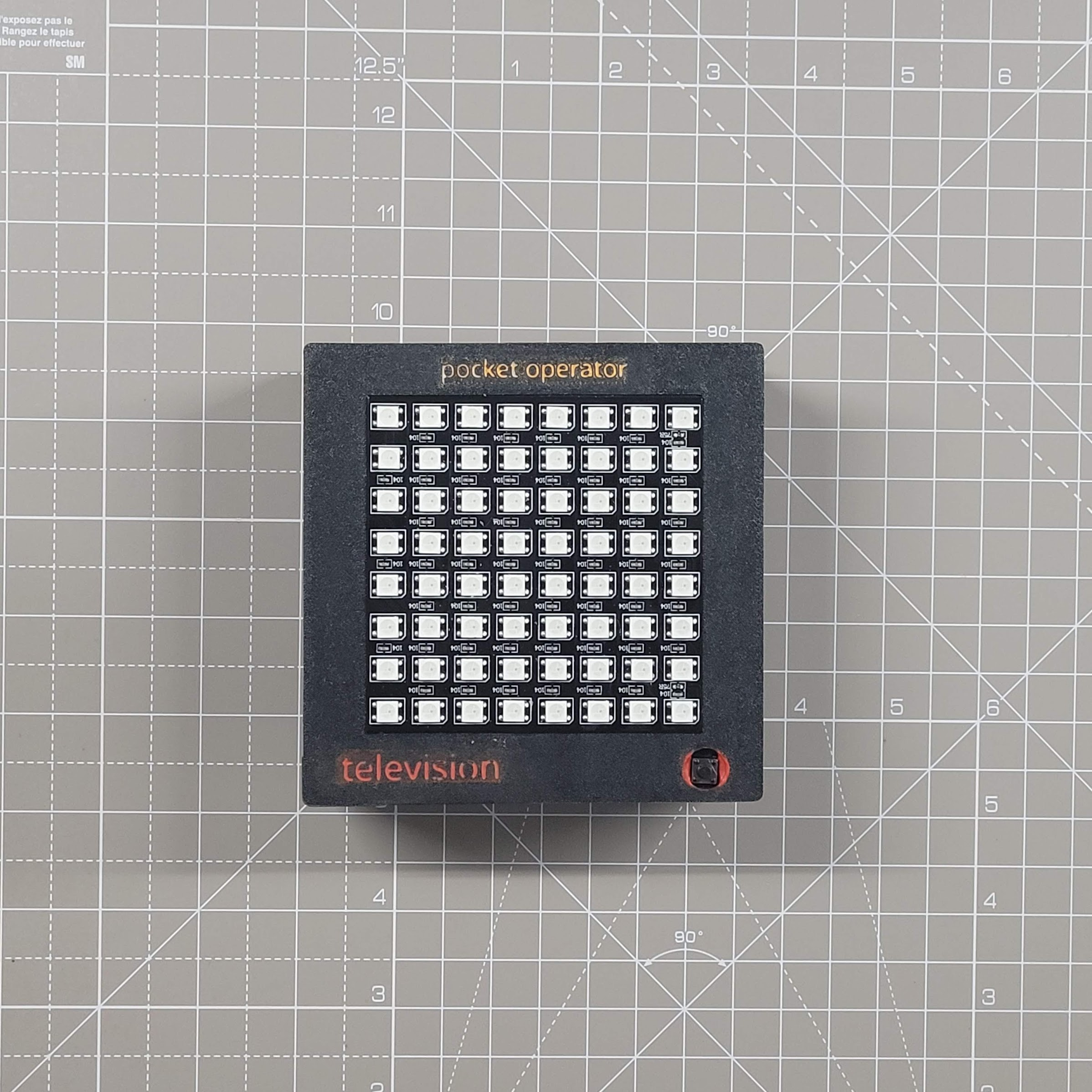
The pocket operator television is made entirely from off-the-shelf components and 3D printed parts. Its design tries to mimic the pocket operator: exposed black circuit boards, gold parts and strong colors in prominent parts. It's easy to build one for yourself!
Electronics
Component List
- 1x Raspberry Pi Pico W – the brains of the PO television
- 2x 3.5m audio jack – this will act as the input and output line of the device
- 1x button – to toggle between animations
- 2x switches – one to turn the device on/off and one to toggle between synchronization modes (
SY4/SY5) - 1x LED matrix display (8x8) – to output our animations
- 1x level shifter – to convert the
3.3Vsignal from the Raspberry Pi into a5Vsignal to send to the display - 1x step-down buck converter – to convert an external power supply to
5Vand power our circuit - 1x AAA battery holder – you can use other power supplies since we will be using a step-down buck converter, but I would recommend AAAs since they are the same ones used in the pocket operator, so you don't need to carry around several different types with you you
- 5x
100k1 ohmresistors, 1x470 ohmresistor and 1x1000uFcapacitor – these will be used throughout the circuit, more details below
The circuit
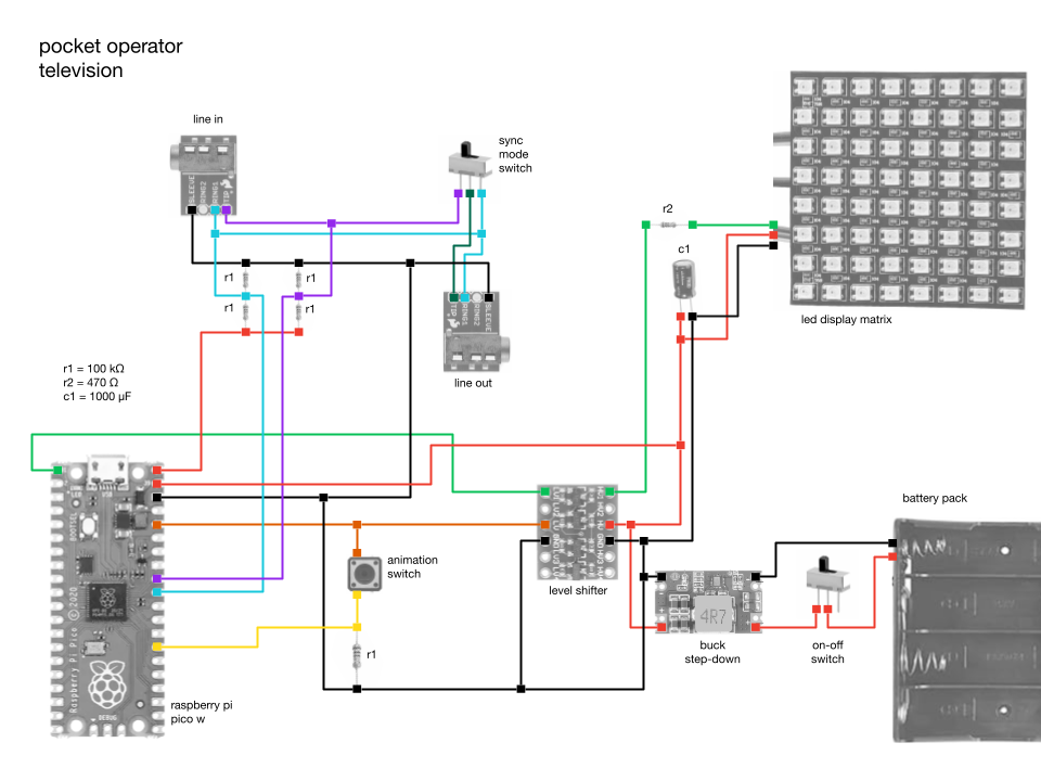
Notes on reading the audio input signal
We want to listen to two signals coming from the line-in of the device: the PO-Sync signal and the audio signal itself. We will pass both of these through a voltage divider (the r1 resistors) rather than reading directly from the source. Since the voltage division is done in half, we don't need to use 100k ohms resistors specifically, you can use any value as long as they are the same.
Notes on connecting the animation switch button
The r1 resistor connected to the power button ensures that we have a ground reference for when the button is not pressed. I used a 100k ohms resistor since I was already using one of the same value in the voltage divider circuit for reading the line-in signal, as explained above. Here, you can also use different values for this resistor in the animation toggle button, if you prefer.
Notes on the PO-Sync Mode Switch
Between the audio input and output, there is a switch that allows you to switch between SY5 mode, which passes the PO-Sync clock signal through to other devices that can be daisy-chained, and SY4 mode, which copies the audio signal to both inputs and allows you to listen to the sound through a speaker or headphones in the line-out.
Notes on connecting the LED matrix display
I connected the LED matrix display as recommended by the Adafruit team in the NeoPixel guide. You can learn more about how to use them properly there, especially if you want to modify your pocket operator television to work with different displays or LED strips.
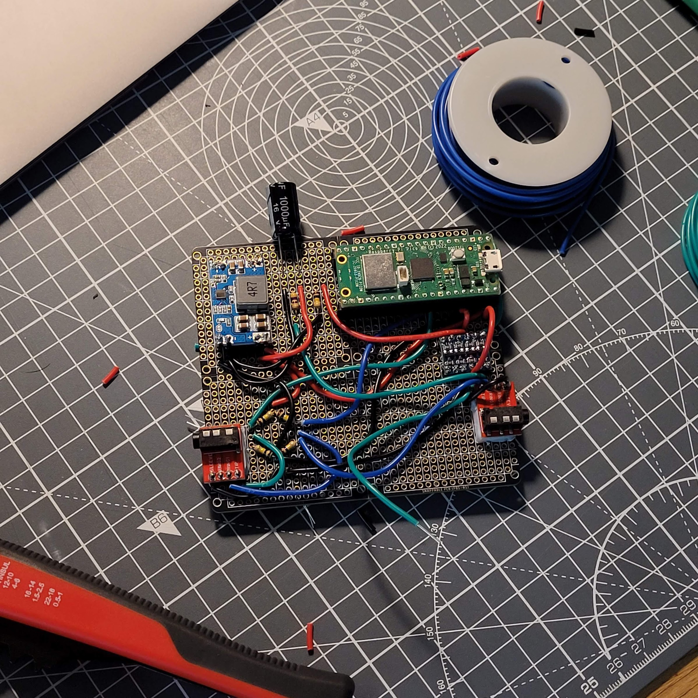
Hardware
To put it all together, after prototyping on a breadboard, I found a black and gold circuit board that was the closest thing I could find to a pocket operator. I wanted the final device to look as much like a pocket operator as possible. I soldered all of the electronic components mentioned above, following the circuit diagram.
The 3D printed case is very simple. It is meant to hold the display, circuit board, and animation toggle button together. The LED matrix display I purchased came with a JST cable soldered to it, so I used that to connect to the board. For consistency, I also used a JST cable to connect the animation toggle button to the circuit board. The main case and back cover can be joined together using M2 screws and nuts.
You can find the 3D models I used in the .stl files in the models folder. Feel free to modify them to better suit your needs, as you may need to change them to fit your circuit board and display if they don't have the same dimensions as mine.
Adding colors in 3D printing
If you have a printer that supports multi-filaments, this step is much easier. Adding some colors in 3D printing will make the pocket operator television look closer to the pocket operator's aesthetic: parts in gold and others in some accent color.
In 3D printing, I added texts and made a small extrusion in them to create a valley, about 0.5 millimeters. Then I came with a brush with acrylic paint in the color I wanted and put the paint inside this small valley. Right after, I passed some paper to clean up any dirt on the outside, leaving only the paint that was stuck inside the text valleys. After two or three layers, the result was reasonable.
Since I built the PO television trying to follow the idea of being able to create your own samples that the PO-33 K.O. offers, I decided to use orange as the highlight color. The "pocket operator" text at the top was in gold and the "television" text and the highlight on the sides of the front button were in orange.
The code
Setup
You can download the repository as a .zip or clone the repository with git clone git@github.com:EEmery/po-television.git. The code uses MicroPython and you will need to install the firmware on your board, but it is a simple process.
Once you have the repository and the firmware installed, we can copy the files from the local src/ folder to the board you are using. This repository sets in the requirements file (requirements/dev.txt) a series of tools to facilitate development with MicroPython, such as thonny, rshell and pipkin. To activate the virtual environment with these tools, simply run the following in your terminal:
-
python3 -m venv .venv -
source .venv/bin/activate -
python3 -m pip install -r requirements/dev.txt
The repository already contains the files for the neopixel library, which is used to communicate with the LED display, so you don't need to install it. But, if you feel the need to reinstall this library, just run the command below while your computer is connected to your board:
python3 -m pipkin install neopixel
To send the code from your local repository to the board, just use the rshell copy command:
rshell cp -r src/* pyboard/
If you prefer to develop with thonny, which is quite popular when it comes to MicroPython development, instead of using pipkin to install the libraries and rshell to send the code to the board, just run:
python3 -m thonny
Diving into the code
The code is quite simple. I developed it with MicroPython, since Python is a popular language among hackers. I haven't used any complex digital signal processing algorithms or anything like that, at least not yet. I encourage you to play around with the code and share your creations. I'm planning to experiment with adding some function that performs a fast Fourier transform (FFT) or other digital signal processing (DSP) functions. It should be interesting to see what we can add to the animation logic to make it respond to more complex information from the music we are playing.
But diving into the code, we basically have something similar to a "sense-plan-act" structure, common in the world of robotics. The code first reads the audio input signal and processes it into parameters that are easier to consume in the following steps.
At each step change (clock pulse), we call the animation function to request a new frame to be displayed. This is the "planning" phase of our framework. We pass to the animation function some parameters that we were able to collect from the pocket operator, so that we can use them (or not) to construct the next frame. The list of parameters can be seen in the code.
The animation function will return 2 parameters. The first is the new frame, which consists of a 2D 8x8 list where each value is a triplet (tuple) representing the pixel's RGB values (red-green-blue). Each element in the pixel can range from 0 to 255. The second value it returns is called memory and should be used however the developer wishes. The idea behind this is to allow any "state" to be passed between the previous function call and the current one, so that the code can "remember" relevant information from its previous executions. This could have been achieved with an object instead of a function, but I feel like it could have made the code a bit more complex to modify, given that a "state" can be achieved with a simple function parameter, like the one we used.
Finally, with a new frame in hand, we update the display with it. This is our "action" stage of the framework and the end. We then proceed to the loop and start "sensing" the signal at the audio input once again.
During this loop, we also keep checking to see if the animation button has been pressed. When this happens, the code switches the animation function from a list of available animation functions for use.
Adding your own animation
Adding your animation is easy, you can start by replicating some of the existing animations to create your own.
-
Robotic arm animation
animation_robot_arm.pyThis is the simplest of all the animation functions. Basically, we have 16 frames in the animation and we iterate one by one as the function is called in a new step. This function does not use most of the arguments passed to it. The code is commented for better understanding.
-
Wave animation
animation_wave.pyThis animation is very similar to the previous one, with the difference that it allows you to use any number of frames, it does not have to be exactly 16, which ends up making the code flexible to be reused frequently.
Here, we save the cursor information of the current animation in memory to remember where we left off in the next function call. This way, we can iterate through the frames one by one. The code is commented for better understanding.
-
Robotic eye animation
animation_robot_eyes.pyAs mentioned before, the animation
animation_wave.pyserves as a good template to be replicated in other animations, since it allows the flexibility of any number of frames. This animation,animation_robot_eyes, is practically a copy ofanimation_wave, with the only difference being the frames used, which form a different drawing. -
Music visualization animation
animation_music_visualization.pyThis is a slightly more complex animation, compared to the others. It serves mainly to demonstrate a possible use of the parameters that are calculated from the audio input of the pocket operator. In it, we draw a representation of the intensity of the sound signal in each of the steps. The code is commented in each step for better understanding.
Add a call to your new animation function
Whether you are copying an existing animation and modifying it or creating a new one from scratch, you need to add a call to the new function in the main loop of the code. To do this, in the main.py file, simply import the function and add it to the list of functions called ANIMATIONS.